Watch Winder
A close friend of mine recently gave me a few watches, one of which being an automatic one. I’ve never owned one before, and upon learning how it works, it occurred to me that I don’t really want to set the watch to the correct time everytime I wear it. Sure it might increase the lifespan since the mechnical parts are moving less often, but I’m placing convience above it.
There’s this clip from the 2016 movie “Dr. Strange”, where the main protagonist before going out for a drive, opens a drawer to which a dozen spinning watches are placed. I wanted to replicate this, so I did. Or at least, sharing my progress halfway into the project.
Design Considerations
I’ve never programmed in assembly before, so I wanted to make this project start with that. Now the architecture. AVR is probably the best bet here, there’s tons of resources available for it, and it’s widely popular for people taking the leap and ripping the MCU from an arduino. ATmega328p it is. Now for spinning the watch. This device has to be silent, ie stepper motors with a Trinamic driver. I found this one with a silent step feature, TMC2100, seems pretty promising.
Layup
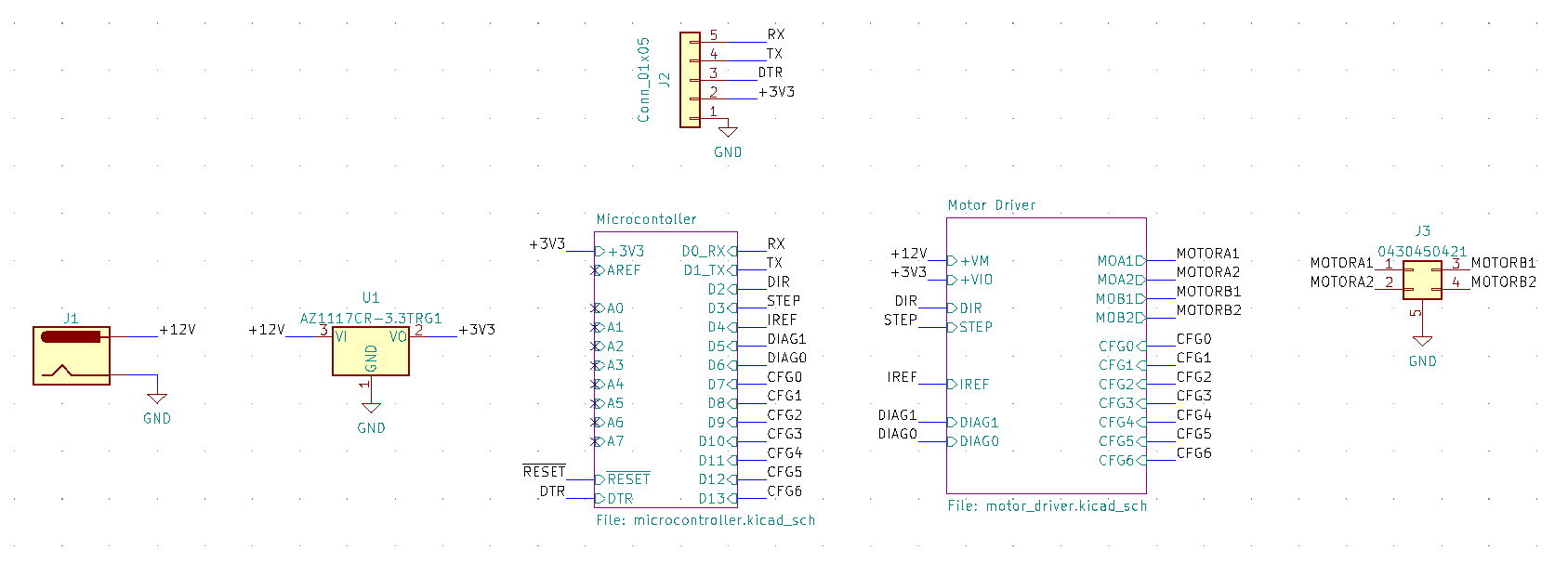
Standard stuff with the schematic, just followed the data sheet for both the MCU and the driver. I decided to opt for barrel jack as the power input. 12V input, which is compatible with this low power stepper I’m using.
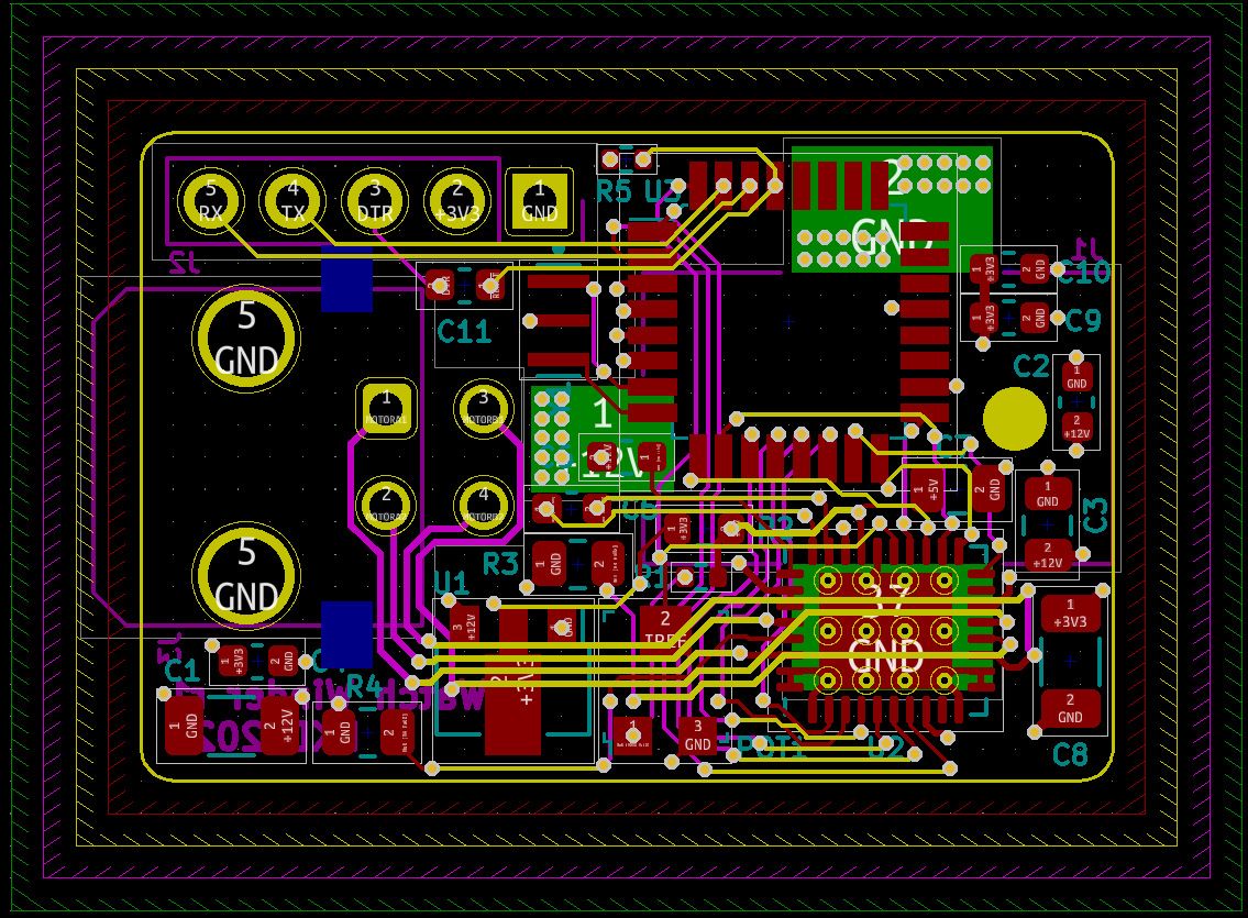
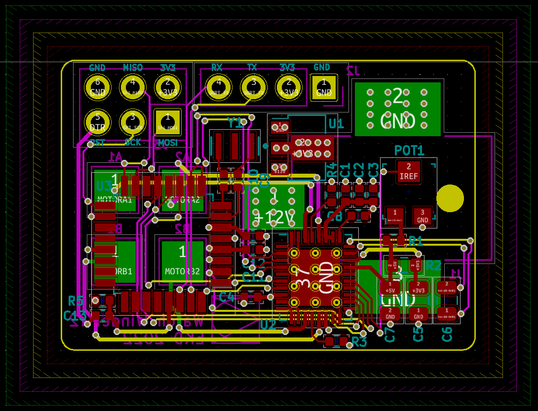
The layout was pretty tricky. I let my ego get in the way to see if I can do this board in only a 30mm by 20mm footprint. Once I got started, I immediately knew this has to be a 4 layer board. No way in hell I can do this in 2. Here it is.
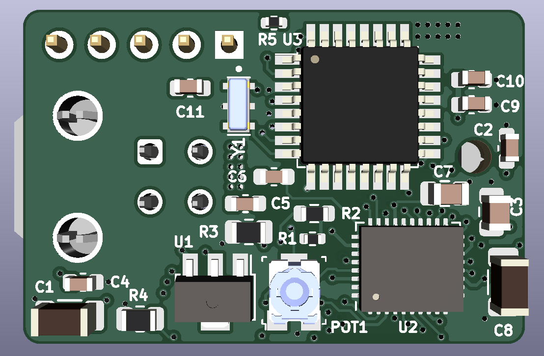
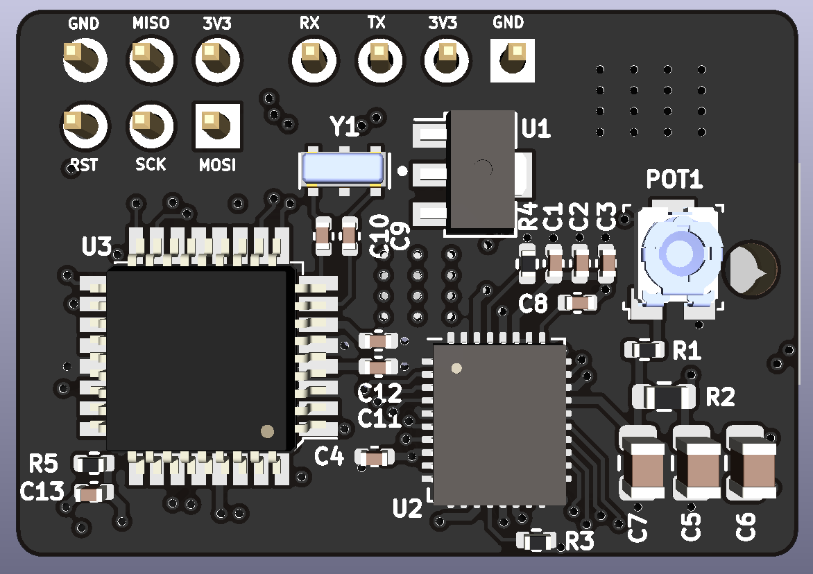
And of course a 3D Model:
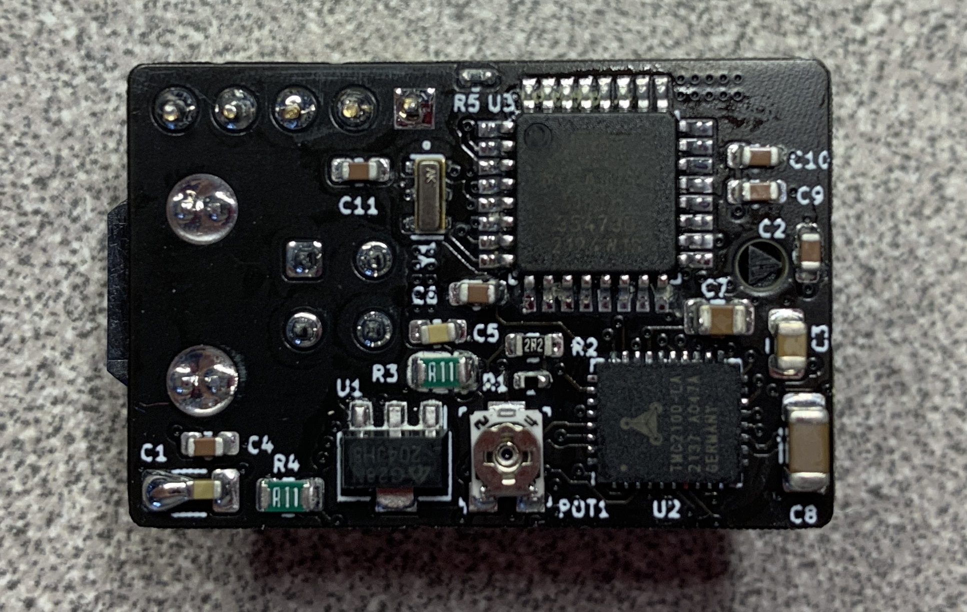
PCBs came in, I’d say they look pretty well done, reflowed all of the components on, the QFN trinamic driver was rather hard to touch up, since the parts were crammed so tightly in. Here is the full PCBA:
Analysis of r1
Obvious packaging mistake on my part… Nothing like a slight-of-solder won’t solve. And it doesn’t hit a current cap when I power it on, so at least they’re no short circuit. I got onto programming it, using avr-dude as the programming application, and AVRA as the assembler. Untested code that should theoretically work is on my git server
Here’s a tip in 2022: buy your chips right after you finish designing. Of course I forgot about the chip shortage, so I thought I could big-brain this situation by ripping the ATmega328p off of an Arduino Nano I had laying around, which is luckily the same chip I designed for. Caveat is that there’s a bootloader preinstalled at the end of the flash memory. I should have done more research into AVR programming, because turns out, you can’t mess with the boot loader if you program using UART, which is the only interface that I designed headers for. Tried a whole bunch of different avr-dude configurations, no luck. Looks like I’m going to have to redo the board, and include header pins for SPI, which I know now is the main way you should be programming this MCU.
Also for some odd reason I suppose I was on autopilot when speccing out the filter caps for the TMC2100, and used the recommended 50V caps, when I know I’m only going to be using a 12V stepper… So instead of paying 3 cents for a cap, paid 3 dollars.
Layup of r2
Finished layup of r2. More detailed change log is in the schematic. The main addition was the ICSP header to program the MCU through SPI. Honestly, I preferred the layout of r1, but r2 is much cleaner.
//Be back in a few weeks…